A Guide to Understanding LiDAR Sensors Function & Capability
When we discuss Geo-MMS LiDAR sensor characteristics, there are many metrics and factors that go into understanding the oftentimes overwhelming information provided by LiDAR sensor manufacturers. This information is being provided so that our customers have a clear vision when it comes to selecting the optimal LiDAR sensor for their Geo-MMS product.
In this study, we will examine several LiDAR sensors supported by the Geo-MMS Family of Products, including sensors from Teledyne Optech, Quanergy and Velodyne.
Light Detection and Ranging (LiDAR) is just one type of active range measurement technology. Other active ranging technologies such as sonar and radar use sound and radio waves as their sensing methods respectively, whilst LiDAR utilizes short wavelength laser light for measuring the distance between the sensor and detected objects.
![]()
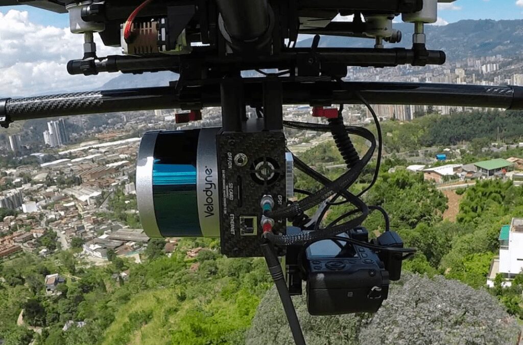
Figure 1. Typical Geo-MMS Point&Pixel system in flight (Velodyne Puck VLP-16 LiDAR)
Points Per Second
Points per Second (PPS) is one of the best metrics to gauge LiDAR system performance, as it multiplies three metrics together: vertical points, horizontal points and frame rate; described respectively here.
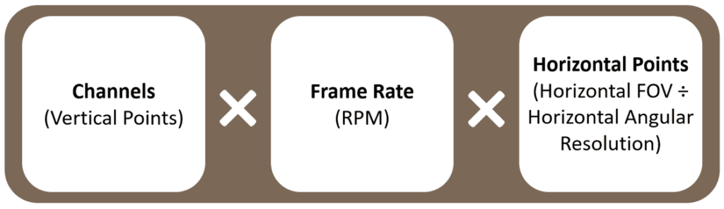
Figure 2. Calculation of Points per Second emitted by spinning analog LiDAR sensors.
- The channels or ‘vertical points’ of a LiDAR sensor is an unvarying number of laser beams, dependent on the sensor (and often indicated in the sensor name e.g. M8, VLP-16, etc.)
- Frame rate is the rotation rate of the sensor (expressed as frequency, Hz)
- The ‘Horizontal points’ can be calculated by dividing the horizontal field-of-view (FOV) by the horizontal angular resolution
- Angular resolution and frame rate are typically provided as ranges in sensor datasheets. The lower angular resolution corresponds to the shorter frame rate, whilst the higher angular resolution corresponds to the higher frame rate.
Frame rate and horizontal points have a tradeoff but are independently configurable. See below an example from the Quanergy M8 Ultra LiDAR sensor.

Table 1. PPS calculation for the Quanergy M8 Ultra LiDAR.
These calculations and metrics are relevant for analog spinning LiDAR sensors, such as the Velodyne and Quanergy models Geodetics integrates with. For more information regarding single laser raster scanning LiDAR systems, please refer to the final section of this blog. Further information will also be presented in the second part of this blog series.
Returns
Each LiDAR pulse will reflect on many objects with different reflectivity properties over a typical UAV-LiDAR mission. An emitted laser pulse that encounters multiple reflection surfaces as it travels towards the target feature is split into as many returns as there are reflective surfaces. The first return is the most significant and is associated with the highest feature in the landscape such as a treetop or a road surface. Multiple returns are capable of detecting the elevations of several objects within the laser footprint of an outgoing laser pulse.
For each return a LiDAR sensor is capable of capturing, the number of points actually reflected in each return decreases significantly. The large majority of points in any LiDAR system will be captured by the first return. Manufacturers who multiply their PPS value by the number of maximal possible returns provide misleading information. The return capability of LiDAR is important for certain applications, but its value should not be overestimated. When mapping over urban areas consisting primarily of building roofs and streets, additional returns offer little benefit. Multiple returns do offer an advantage when operating over vegetated areas, as the different returns penetrate through vegetation to capture accurate and dense ground point measurements beneath forested or vegetated areas – something that is fundamentally lacking in photogrammetry.
Takeaway: Multiple returns don’t increase your PPS linearly with the number of returns possible. Actual returns are based upon object reflectance.
Sensor Type | Beam Divergence
Geodetics’ long-range LiDAR option integrates a raster scanning LiDAR sensor which has a different sensor architecture compared to the aforementioned spinning sensors. These sensors utilize a single laser and a mechanically oscillating mirror. Points per second is a function of the scan speed (mirror oscillation) and Pulse Repetition Frequency (PRF). The Teledyne Optech CL-360 is a single laser LiDAR, whilst frame rate is expressed in the form of Pulse Repetition Frequency (PRF) – the number of repeating pulse signals over a specific time unit, measured in pulses per second.
Beam divergence represents the deviation of photons from a single beam emitted by a LiDAR sensor. Because each laser pulse is emitted in a cone shape, the intensity of the laser pulse decays exponentially over distance. This is one of the areas where the raster scan systems hold a distinct advantage. Beam divergence for the Teledyne Optech CL-360 is 0.3mrad, while spinning sensors diverge the laser energy by ~3mrad. Because the total amount of pulse energy remains constant regardless of the beam divergence, a larger beam divergence leads the pulse energy to be spread over a larger area, leading to a lower signal-to-noise ratio. This is part of the reasoning for the recommendation to fly at a low AGL for UAV-LiDAR missions.
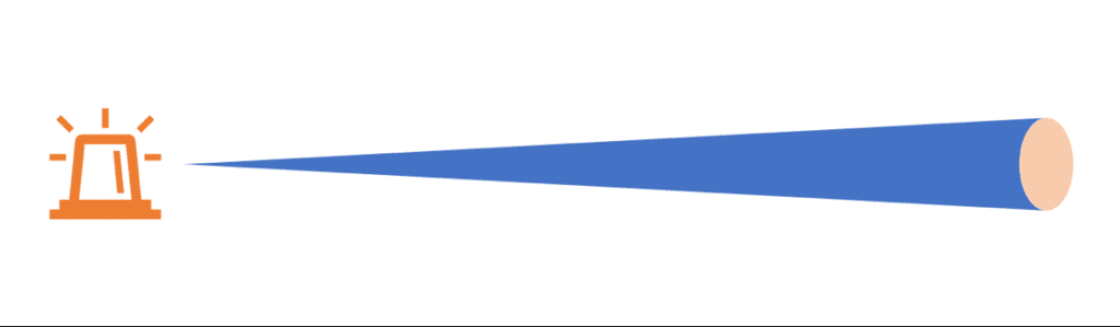
Figure 4. Figure displaying the beam divergence of a laser pulse as it is emitted from a sensor.
In the second part of this series, we will explore the differences between raster scan and spinning LiDAR sensors including the laser types used in each. We will also examine more closely other commonly used metrics including range, LiDAR precision and system ruggedness and durability. For any questions relating to LiDAR sensors or your project in general, please Request more Information.
Originally published by Geodetics